When Jordan Monson joined Willow Creek South Barrington’s staff as Lighting Engineer, our LED game grew significantly stronger. Jordan came from designing, building and programming light suits for the dance company iLuminate, and over 6 years experience working with various forms of LEDs and alternative lighting products. In this article, Jordan outlines his workflow, process, and some key learnings.
 The Idea
The start of any good scenic LED process is the original idea. It could be based on an image from Google, a magazine article, or something no one has ever seen before. The important thing is to have a concept and know what you’d like it to be able to do. If you don’t know what your target is, you’re a lot less likely to reach your goal.
In my role as Lighting Engineer, I am often in the initial ideation conversations with the scenic designer and the creative director. In this stage, our discussions are centered around desired moments of feeling – where the lighting and set are co-creating a certain environmental feel. When LEDs are a player in the scenic set, they bring color and energy to the set through creating or augmenting a specific feeling in a moment. Knowing what the expectation is for the design is extremely important for achieving both a solid design and keeping the surprises down the road to a minimum.
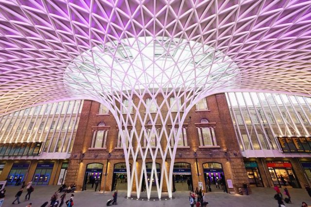
In our initial meetings about what has come to be known as “The Waffle Fry” set, the set’s designer, Jim DeLaere, and I started talking about using analog RGB LED tape for accenting the layers of the set. I’ve developed an aversion over time to adding raw LED tape to things. I would much rather have something that disappears into the set when it is not in use. From an artistic perspective, our creative team wanted to be able to light up a bowl shape on the set for an actor to trace with his hands and create a star field effect from projection/lighting for another moment. With these goals in mind, I suggested we look at using a digital LED product that in my iLuminate days we referred to as bullet LEDs. With enough of the set covered in bullet LEDs, we could do both the bowl and the star field as well instead of using projection or lighting gobos.
![]()
![]()
The Plan
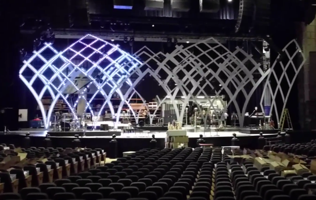
Now that we had some concepts roughed in, we moved on to the Planning Phase. I dove into researching, budgeting, and ordering all of the necessary items to execute our ideas. Based on our pre-visualization plans and creative goals, the next step was finding a product that would fulfill our requirements. I settled on two products from Holiday Coro: RGB LED Nodes with 6” spacing and Alpha Pix 16 16-channel controllers. Because we ended up selecting LED nodes with 6” spacing, we significantly lowered our total led costs compared to using standard LED tape. One strand of nodes got us a little over 25’ of coverage. So instead of a single layer of our set, we were able to cover the entire set with LED. This fulfilled our creative goals of tracing a bowl on the set as well as giving us a killer starfield effect. Fun Fact – This set had over 7000 individual pixels, and contained about 4500’ of LEDs total.
From a pre-visualization standpoint, we planned the layout of the individual LED nodes, where controllers would be hidden in the set, making sure we had enough power to drive the LEDs, and making a plan for addressing all of the nodes. All of this planning also played a big part in programming our pixel-mapping software to make sure everything will display properly.
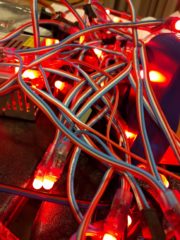
Up next on our planning list was figuring out how to integrate all of this gear into the set and be done before Christmas. Seems easy enough, right? In order to save time, I had decided to go with a small Molex connector crimped on each LED string so I could use custom cable lengths and replace single LEDs without soldering. I estimated the number of hours it would take for crimping connectors on all the LED node strings, found some friends willing to help me do the work, as well as to test every string and controller since we hadn’t worked with the gear before. After a couple of long evenings spent in a room with these guys listening to a mix of punk rock and electronica, we finally finished crimping ends on everything and did a full system test. Now we were ready to install them on the set.
Let’s be real – I love spreadsheets and make at least one for every project I do. They contain every detail I need to keep track of – the budget, parts list, labor plan, and extend all the way to the nitty-gritty details of my controller IP addresses, what every output of each controller is plugging into, the pixels per output, power draw per output, and the power draw per controller. Having a written plan that goes into this amount of detail helps me pre-plan so that I’m making the most of my time and my team’s time once we get to install day. It is also a great tool to hand off to other team members so that they can be self-sufficient once they understand the install process and troubleshoot accordingly.
 The Installation
During the install process, changes are going to happen – it’s a fact of life. Even with this in mind, it is extremely important with digital LEDs to stick to the plan, and if the plan needs to shift, make sure to update your spreadsheet and communicate the changes to your team. Things like skipping an LED, or a string being installed backward may seem like a small deal in the beginning but can add hours to programming the system and troubleshooting process.
I made a design document for the installation team that showed where and how each LED string should run, the number of LEDs in that path, and the channel on the controller to plug into.
In the design process, we had decided to build the majority of the set out of pink insulation foam with holes drilled every ~6” for the LED nodes to poke into. (Along the way, we learned that because of the foam thickness we used the LEDs didn’t get enough air flow around them and we had a good number of strings with pixels that would lose a color and require replacing of the LED node. Lesson learned…) We layed out each layer of scenic foam and installed all the LEDs for that layer before hanging the piece so that we wouldn’t have to do any additional work in the air. The controllers and cable paths ended up landing on the flyhouse batten that the set pieces were hung from. We started the wiring of the LED strings as close to the controller as we could make them to keep cable lengths shorter.
 The Programming
Now that everything has been physically installed, it’s time to program. The theory for how to program is dependent on your method of pushing DMX data to the pixels. Some just use a lighting console, some use a full-blown server to do video mapping to the pixels, some people a combo of both. At Willow, we use a media server called D3 (ok well the company changed their name to Disguise but it will always be D3 in my heart). Though it has amazing power, it is not a very user-friendly server and is missing some key functions like zigzag addressing that would streamline the process greatly. No matter what you use, the goal in this part of the process is to layout and address every LED on your stage in a way that allows you to control it as a part of the broader picture of your lighting rig. We use a .obj file exported from the CAD file of the set to import a 3D model of the set into D3. From there, I lay out led strings on top of the set model in the D3 as close to where they land in physical space as I can.
Once I had all the LEDs programmed into the D3, I individually addressed and tested each strand – making sure they are in the right place according to my documentation and what I see in real life. This process consists of lighting up each individual strand of the set with the same piece of bright motion content, setting the start address, pixel length, and starting direction of every string, finishing by making sure it looks correct. Next, I double check the LED positions and string directions with content that moves horizontally, and then vertically.
Now that the LEDs were mapped correctly, the next step was to set up layers in the D3 to do what the scenic designer envisioned in the idea phase. I set up a mapping layer that was just the centermost lines of the set that made a bowl shape over the center of the stage, and built a keyframed solid white clip that expanded from the center of the bowl to fill it out as the actor drew it in the sky. Next, I made a layer that had the whole set and our homebrew LED wall and found a cosmos video clip that created a star field. These moments were adjusted a lot once we got into rehearsal, but we had workable proof of concept right away so we could see what adjustments needed to be made.
Thanks for taking the time to read through my process! I hope that you were able to learn something from my thoughts and process when working with Scenic LEDs Pixels. My process isn’t perfect, heck before today I hadn’t written any part of my process down. I am always learning and trying to improve and streamline how I work so if you have any questions, or suggestions please leave a comment below.